In this post, I implement a real time depth map segmentation system, based on normal map analysis.
Depth map analysis (as obtained by a RGB-D camera for example) is not an easy or fast task. The target of this post is simply to implement a method to segment elements from a depth map, like objects, planes, any closed 3D surface in fact.
As always, I have a certain aversion (mistrust ?) toward neural networks, so I’m trying my best without them a try to use them when the condition of failure for them are minimal. The state-of-the-art real time depth map segmentation method ([4]) uses a normal map segmentation (as in [1], [2] ans [3]) in addition to a simple neural network for class proposition. As I have absolutely no use for classes here, I will only use normal separation.
A little reminder in depth maps:
- A depth map is an image in which each pixel is a distance measurement
- The holes (0 values) in depth maps are a lack of data
Fix the depth map
To fix some defaults in the depth map in prevision to it’s use in normal calculation, I applied some treatments to it.
Here I used a morphological closing, a median filtering and a bilateral filtering, which aim (in order) at closing the little holes, smooth those modifications and smooth the whole image while keeping the edges.
cv::Mat newTempoMat
cv::morphologyEx(depthMap, newTempoMat, cv::MORPH_CLOSE, kernel); // kernel is a 3x3 square
cv::medianBlur(newTempoMat, newTempoMat, 3);
cv::bilateralFilter(newTempoMat, depthMap,  7, 31, 15);
The papers I used as references are all using a vertex map, which is a depth map converted as “real” units. I will consider in this post that my depth map is a vertex map (that’s true, I just call it a depth map).
Compute Normal Map
A normal map is a RGB image which represents the normal vectors of each pixel to its neighbors (see Wikipedia: Normal (Geometry) for more details as I wwon’t go further here).
This structure is made of NxM 3D vectors for a NxM sized image, and is stored as an RGB image with each channel as a vector component (smart !). The final effect is a blue/green/red nuanced image, depending on the direction of the prevailing normal direction (see Blog de Fabrice Bouyé (French) for nice and clear pictures)
A normal map from simulated data is rather “nice”. It displays clear color gradients (low noise), but that won’t be the case in our real measures.
We can get the normal to a depth point (x, y) with the following C++ code:
float dzdx = ( depthMap.at<float>(x + 1, y) - depthMap.at<float>(x - 1, y) ) / 2.0;
float dzdy = ( depthMap.at<float>(x, y + 1) - depthMap.at<float>(x, y + 1) ) / 2.0;
normalMap.at<Vec3f>(x, y) = cv::normalize( cv::Vec3f(-dzdx, -dzdy, -1.0));
Of course, the holes in the depth map are ignored.
 RGB image, depth map, normal map.
On the normal map, we can see artifacts (vertical cyan colored lines), probably from the depth map smoothing. We also see that planar surfaces (the floor and drawer doors) have significant noise (not even mentioning background features). Those errors in the normal come from the depth map measurement error (see [6] for a noise modelization).
I also added a 3x3 median filtering to the final normal map to reduce noise.
Concave Surface Detection
We then parse the normal map to detect concave features.
I used an operator adapted from [1] which compares a point (x, y) convexity with its neighboring points (xn, yn):
const cv::Vec3f& centerNormal = normalMap.at<cv::Vec3f>(x, y); //normal in the center of the zone to consider
const float& centerDepth = depthMap.at<float>(x, y);           //depth map value at the centre
float minConcavity = 1;
for( each neigbor ) {
    float neightborDepth = depthMap.at<float>(xn, yn);
    double vertexDot = centerVertex.dot(cv::Vec3f(xn - x, yn - y, neightborDepth - centerDepth));
    if ( vertexDot <= 0 ) {
        minConcavity = std::min(minConcavity, centerNormal.dot( normalMap.at<cv::Vec3f>(xn, yn) );
    }
}
thresholdedConcavity = minConcavity > 0.94;
I also added to this a method for [2] and [5] to greatly reduce normal map error, not presented here.
The result of the concavity map (before applying the threshold):
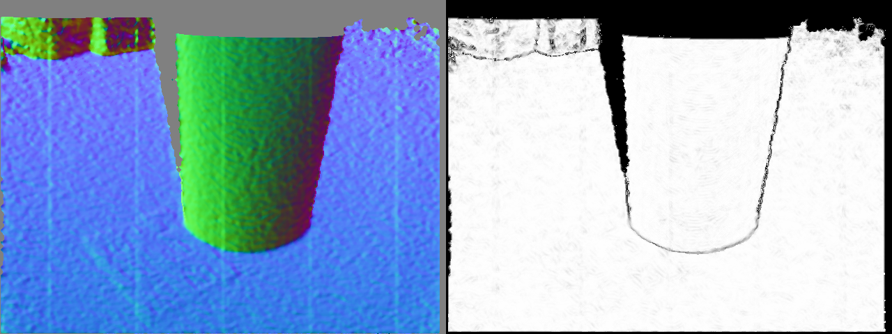
A threshold of 0.94 is applied to this image (as in [1]) to get the concave edges.
Surface Discontinuity Detection
For this step, we want to find depth discontinuities.
I used the same operator as [1], which compared a point (x, y) distance to it’s neighbors (xn, yn):
const float& centerDepth = depthMap.at<float>(x, y);           //depth map value in the center
float maxDiscontinuity = 0;
for( each neigbor ) {
    float neightborDepth = depthMap.at<float>(xn, yn);
    double vertexDot = centerVertex.dot(cv::Vec3f(xn - x, yn - y, neightborDepth - centerDepth));
    maxDiscontinuity = std::max( maxDiscontinuity, abs(vertexDot) );
}
thresholdedDiscontinuity = maxDiscontinuity < (0.12 + 0.19 * pow(centerDepth - 40, 2.0));  //noise model from [6]
The last line shows the threshold for the discontinuity value, depending on the current point depth, extracted from the noise model of a Kinect.
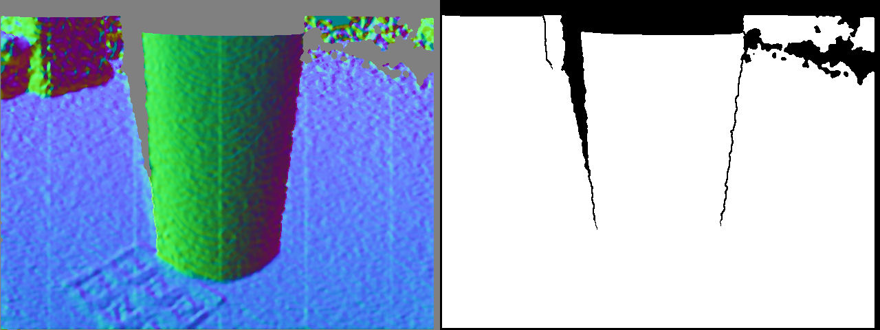
We will now merge the concavity and discontinuity map to obtain an edge map.
Edge Map
Concavity and discontinuity map are merged with a binary AND operator & to obtain the edge map:
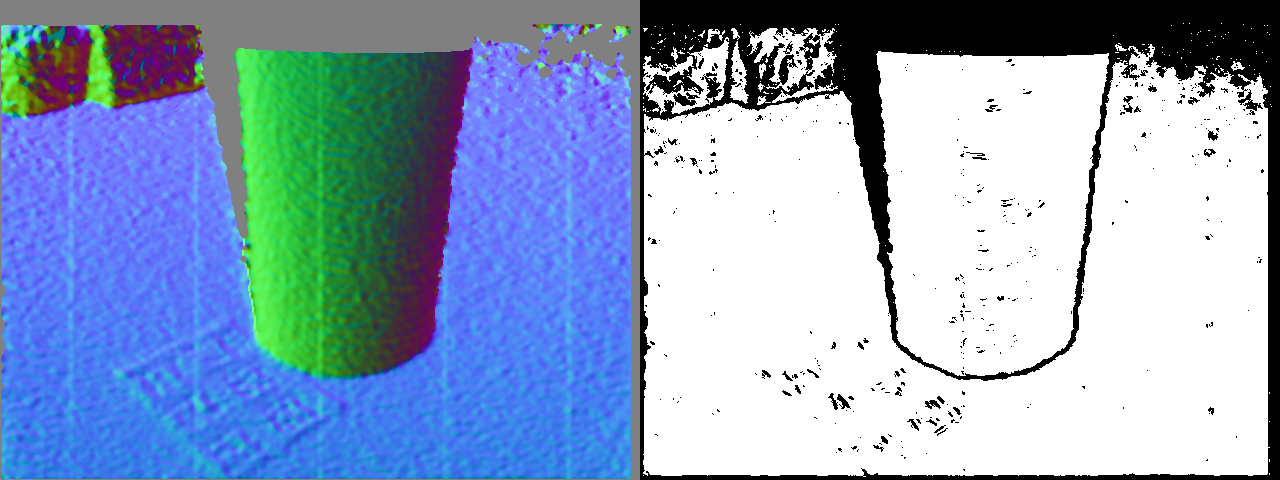
This edge map can than be smoothed with a geodesic closing followed by a morphological opening to filter smaller elements.
Components segmentation
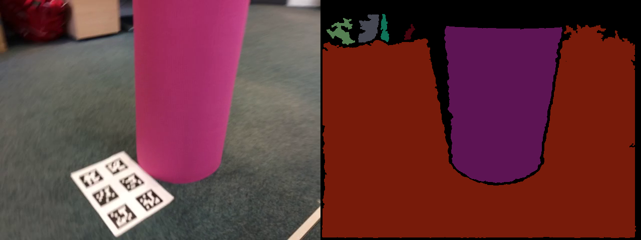
Now, a simple 4 neighbors connected component extraction to get back a segmented depth map. I also filtered the components with a small area to remove small outliers.
To optimize the final result treatment time, I implemented the whole system with a scale parameter to reduce the depth map size. The whole treatment on the 640x480 pixel depth map is pretty CPU intensive, and the depth map is reduced by a scale parameter (0.45 for optimal performances/precision).
Here is the final segmentation result next to the original RGB image.
Qualitative Comparison
As an indication, here is a comparison with the segmented map obtained by CAPE, a system able to detect only (but reliably !) planes and cylinders.
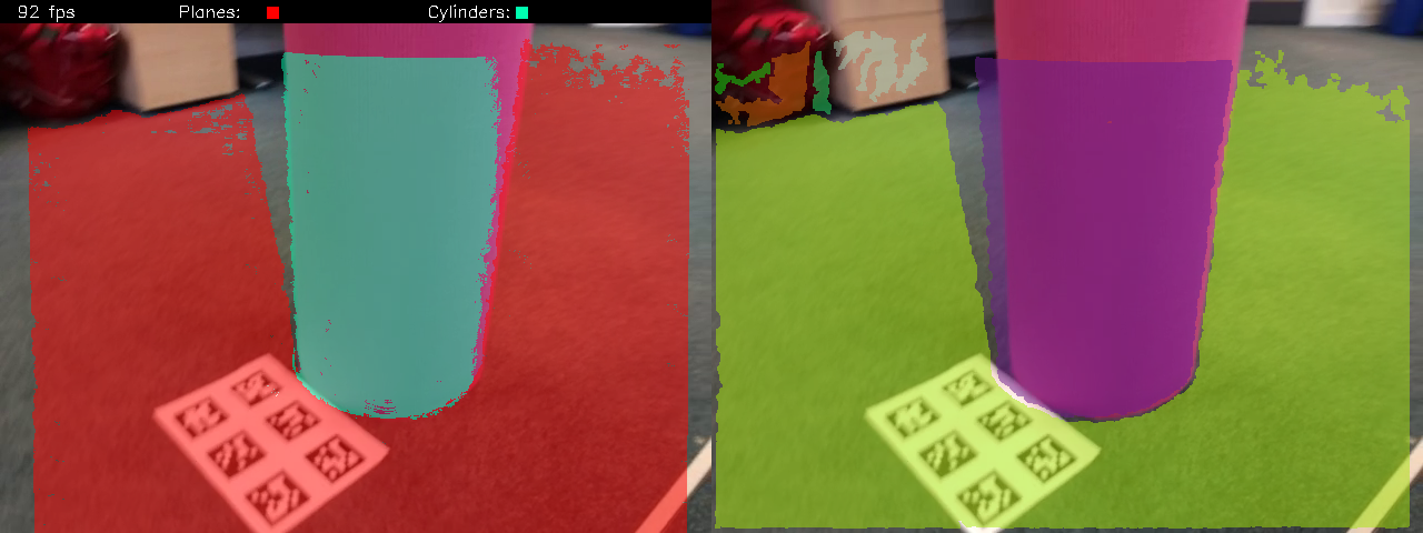 Left is the CAPE segmentation, right is this method (scale=1).
Here CAPE gives us better results, because this scene is made mainly of planes and cylinders, but we can expect that the presented method can handle objects of any shapes. This method also detects surfaces not picked up by CAPE in the background. It is also more heavy to run than CAPE, but is highly parallelizable.
In conclusion, those two methods can be merged to take advantages their strength.
For better mask reconstruction, this system misses a map constructed in memory, which transforms the system in a SLAM (like in [1]).
Bibliography:
- [1] Real-Time and Scalable Incremental Segmentation on Dense SLAM
- [2] 3D scene segmentation for autonomous robot grasping
- [3] KinectFusion: Real-time 3D reconstruction and interaction using a moving depth camera
- [4] Fast and Accurate Semantic Mapping through Geometric-based Incremental Segmentation
- [5] Generative Cognitive Representation for Embodied Agents
- [6] Modeling Kinect Sensor Noise for Improved 3D Reconstruction and Tracking