Use a video taken by a single camera to estimate the depth of objects in an image. A small dip in the world of epipolar geometry and key points analysis.
Depths maps ?
Usually, if you want to give your vision system a sense of depth, you have a few options :
- Stereo vision: Use two cameras and a bit a smart
- Monocular vision: Use one camera and a bit more smart
- Use a RGB-D Camera.
Stereo vision is great, but computationally intensive, monocular vision can work with machine learning or extending the system to stereo (more on that later), RGB-D is super reliable but works best inside and only at close range.
Well, I don’t have two cameras, but what I got is the best kind of cams: an RGB-D one (I absolutely love depth cameras) ! This cam is great, but the depth estimation depends exclusively on an infrared projection. The estimated depth is disturbed by a few factors, including (but not limited to):
- Dark surfaces
- Reflective surfaces
- Small textures (ie: Carpet)
- Sunlight
- Occlusion
- Distance (4-5 meters)
Exemple of an incomplete depth map (dataset: yoga_mat from CAPE):

You can observe holes from depth discontinuity/occlusion (left of the cylinder), and holes from transformation at the top and right of the depth image. The lines of holes in the ground are due to the discrete nature of the depth measurement.
There is a good number of methods to fill those holes (Gaussian fusion, Machine learning, …), but I wanted to take my shot at it with a simple idea : What about merging the information of the depth map with another depth map, less accurate but more reliable ?
Well I have a RGB cam tied to my depth camera (has the name “RGB-D” implies), let’s try to get a depth estimation from the RGB cam.
The first step is to get the monocular depth map. Let’s get into it.
Monocular depth map
Well, how do you make a depth estimation from a single image ? There are not a lot of answers, most of them will scream “neural networks” !
But as our Mentor Master Yoda said,
 Thanks Yoda !
We can try to use two following images in a video as two images taken from a stereo system, while not knowing the transformation between the two images. And you know what ? We can deduce this transformation pretty easily.
The key to this whole story as a name : Epipolar geometry. I won’t get into the details and try to approximate the whole operation in one sentence: epipolar geometry estimates a transformation of one image into the other one.
The logic behind this operation is pretty simple:
- get the key points of the two images
- match the key points, remove outliers
- Estimate the transformation of the points from the first image to get the points of the other one.
- Estimate the disparity map (sort of depth map)
All of those operations can be done with OpenCV.
Key points
To find the key points, I used the OpenCV SURF feature detector. Those key points can then be matched using the OpenCV DescriptorMatcher, using FLANN.
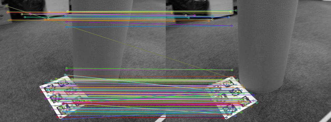
We than get matched pairs, that we can prune based on their distances to the target point, and obtain a clean list of matched points.
In the above image, we can see at least two outliers (key points wrongly matched). Those outliers will be eliminated by the distance check mentioned earlier, or will be removed by the next step.
Details on epipolar projection
A quick note: Epipolar projection of the two images will deform them so two matched keypoints will be placed on the same straight line on the two images. Here, it almost looks like it’s already the case: it’s due to the proximity of the two images in time. A better visualization (and in depth explanations !) can be seen on the OpenCV page.
Fundamental Matrix
OpenCV will also help use with the “Estimate the transformation” step.
Calling the function cv::findHomography with the matched points pairs will return a fundamental matrix, that we can use to warp the second image with (cv::warpPerspective).
I used findHomography with a cv::FM_RANSAC parameter.
We can also get back the in/outliers list (as a vector) to further prune the points of interest (We don’t really need them here).
Details on RANSAC
RANSAC (RANdom SAmple Consensus) is a great method (unfortunately non-deterministic), that I advise you to take a look at. It is able to detect outliers in data. In our case, we use it to find the optimal transformation matrix without being affected by outliers.
Ransac can be used for a lot more use cases of course ! I also used it to extract cylinders from a plane graph, like CAPE did.
Stereo matching
The last trick to obtain the depth map is as simple as the previous one.
We call once more to our glorious OpenCV, with the class StereoSGBM.
This class should be used with a stereo setup, but now that our two images are projected correctly, nobody will stop us from pretending they are from a stereo setup.
Well, the result is not too bad (after a lot of parameters tuning)
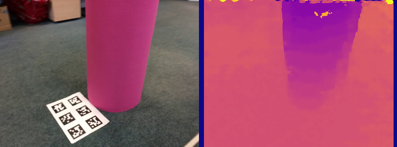
There are a few holes, some discontinuities in the depth estimations and some aberrations in the estimations at the top of the cylinder, but overall it’s pretty good.
I selected a clean image for demonstration purposes but most of them are still super noisy.
Just for the kicks, here is the raw version, with default parameters :
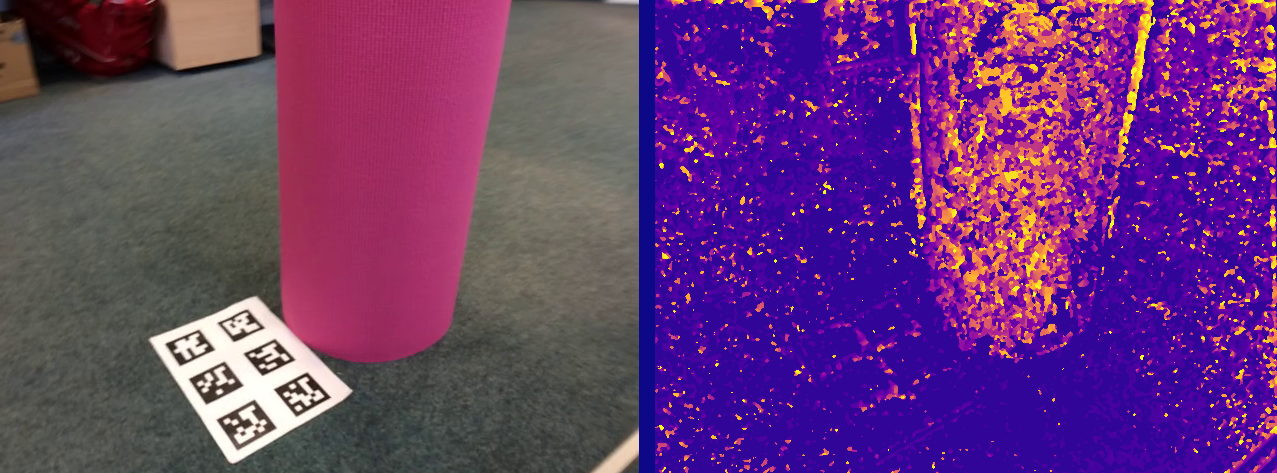
We can clearly see that some flat textures are displayed as depth features (like the QR codes). This is also the case in the top image, but the difference is less visible.
Filtering step
The last step for now is to filter a bit our estimation, to obtain a cleaner depth map.
For this purpose, I use a DisparityWLSDFilter from cv::ximgproc, normally use with a true stereo system.
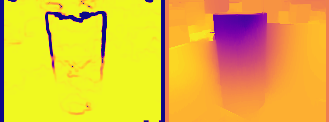
The final result can be observed below, with the monocular generated depth map to the left, and the depth map from the depth camera to the right for comparison purposes :
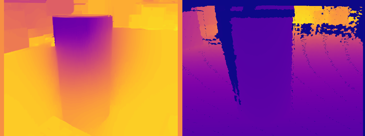
Overall, the final result is pretty good ! Better than expected at least.
Compared to the raw depth map, the monocular shows less holes and errors (they are supposed to be exactly the same). Some points need to be addressed :
- The final monocular depth map does not have any units (meters, mm, …) and thus as no use for me in this state
- The filtering process “leaked” some depth information on the side of the cylinder (darker background)
- The texture of the QR codes can still be seen on the ground, and create a depth error.
- The top of the cylinder is displayed has being closer to the observer than the ground under it, and we can see that it is wrong (from the true depth image).
Another important point, and I did not mention it at all for this entire process: Monocular depth map cannot be as good as a stereo depth map. Stereo generated depth map are much more reliable and precise. They also give us a real measurable depth, as the distance between the two cameras is precisely known.
The quality of depth estimation depends a lot on this distance: basic trigonometry indicates that the depth estimation will be OK only in a comparable scale as this distance. Here, my “two” cameras are each separated by a very small-time/distance, has they are two following frames of a video. The quality of the depth estimation will only be valuable for short distances, experimentally at 2 meters in my case.
But even with those imperfections, this monocular depth map can be used to extract useful information, and that’s what I will do in the next part : Depth map Merging.
Little Bonus
Here is the result of the error map, straight out of the filter. As expected, errors are for the most part located at the depth discontinuity points.