Tutorial on building a compact and sturdy lantern.

Where did the idea come from? (click to expand)
A few years ago, while navigating dark corridors equipped with my €10 Decathlon headlamp, I encountered a friendly guy with a large candle-colored lantern. Homemade, he said! (dedication to my friend Michel)
Well, I had to make one too. With his advice and help, I built a lantern with the same functionality: 18 18650 batteries, 3-4 meters of LED strip, a PWM controller (with a switch) to adjust brightness, and a BMS, all in a 10cm diameter PVC tube. Simple and effective.
However, it was also really heavy and impractical to carry during our (many!) explorations.
So, I decided to create a compact, sturdy, and (probably?) waterproof version.
The tutorial below explains how to build version 0 of the Lamp-da. V0 is the result of 6 or 7 construction iterations, where various improvements were made (the internet is not always a great help…)
Bill of Materials (BOM):
Electronics
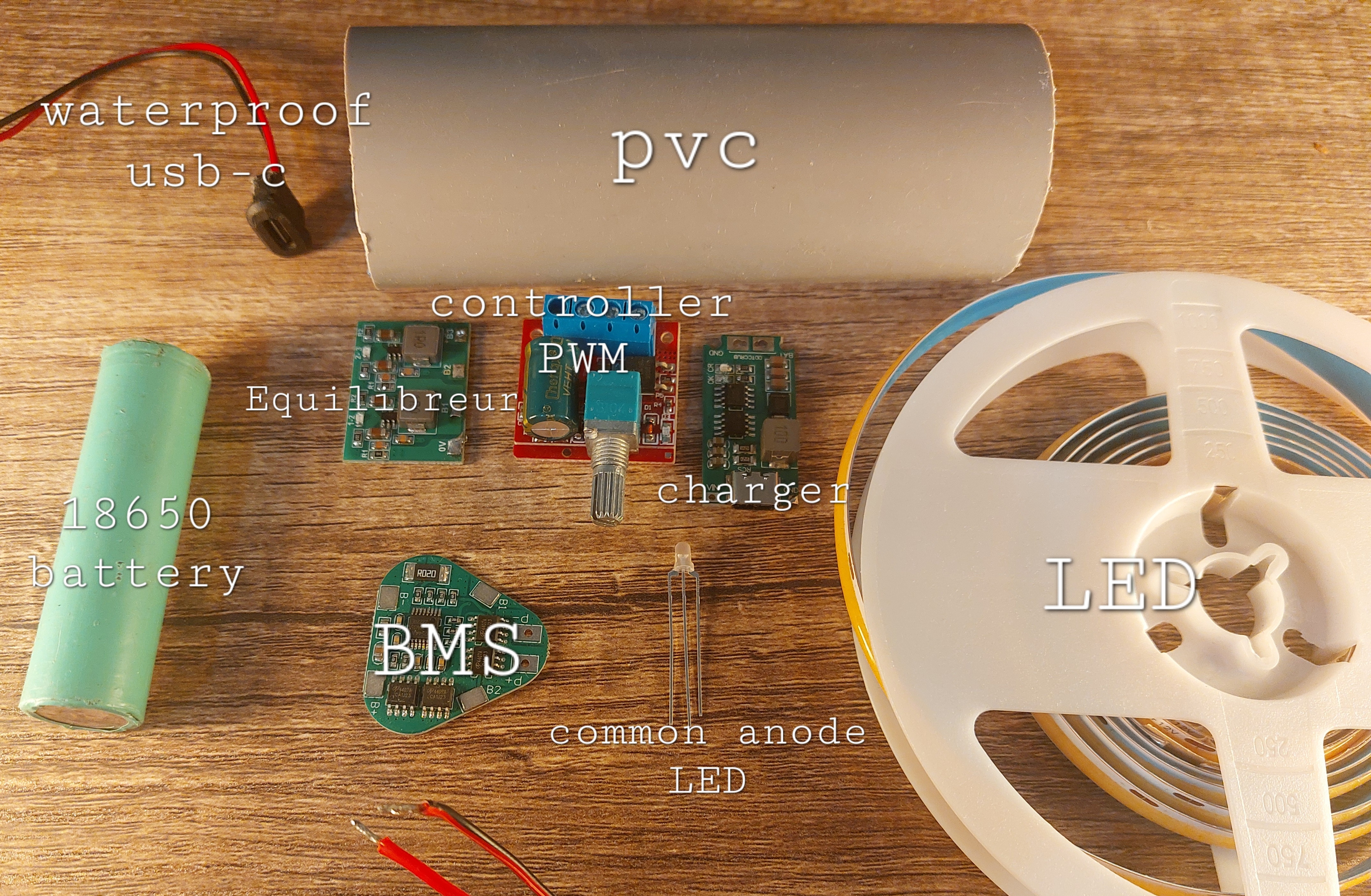
- 12V LED strip, 2800k color: 2 meters. COB type for a unique and pleasant look.
- 3 18650 li-ion batteries. Choose the highest mAH possible (5000mAH for these types of batteries). I use 3500mAh ones (exact ref: LG INR18650-M36 3450mAh - 5A).
- Li-ion 3S BMS: choose a triangle format, at least 2A discharge current.
- Li-ion 3S 12V charger: preferably, use a fast charge-compatible charger, which is not the case with the one presented here. Here, I use a 3S Li-ion 4-amp charger.
- PWM controller. Minimum 2A output current.
- Li-ion 3S balancer (active or passive, doesn’t matter): used to equalize the voltage between batteries.
- Bi-color LED (red/green) common anode.
- Waterproof USB-C connector.
- Electrical wires. The wire I use supports the following specifications: 60V, Max current 4.3A. Choose wire that can withstand more than the maximum current consumed by the LED strips and the charger (here, 2A).
Calculating how to choose components (click to expand)
Let’s do some math to understand what we’re doing:
We use three batteries in series. To obtain the total power stored in the battery, take the capacity of on battery (The capacity does not augment when using batteries in series) 3500mAh => 3.5Ah
It means that our battery can power 3.5A (that’s a lot) for 1h, or something smaller for a longer time. If we want to power something for 20 hours using this battery, this thing must use less than 3.5Ah / 20h -> 0.175A -> 175mA.
(For comparison, the battery of the iPhone 15 is about 3000mAh. but it’s output voltage in about 3.7V, our is around 12V)
More about battery pack design here
Batteries also have a maximum discharge current, indicated at the time of purchase. This current must be higher than the maximum consumption of the system! Here, I have 5A batteries, so my battery can output 5A (Amperes do not add up in serie).
To protect our batteries, we need to choose a Battery Management System (BMS) that can handle less than what our batteries can provide (in this case 5A), but more than what our system consumes at maximum (2A, calculated later) in order to supply it. We should select batteries with an individual max discharge current greater than the consumption of our system.
Then we need a BMS whose protection value is below 5A (battery power) and above 2A (system consumption). The one I have selected has a rating of 4A, but be cautious about AliExpress specs. We can also choose a BMS that matches the maximum output power of our system (2A as calculated just after).
We can also calculate the system’s consumption. We need the LED consumption for that. It is often given in Watt/meters (12W/m for mine). Our LEDs consume at 12V, so we can calculate the instantaneous consumption of the strip (at full power): 10W / 12V => 0.83A/m.
We use 2 meters of LED, so we will consume 0.83A/m * 2m => 1.66A for our entire strip. The minmum consumption that I was hable to measure is around 0.3A before the LED turn off.
Okay, we now have the max consumption and the power of the batteries, we can calculate the maximum usage time: 3.5Ah / 0.3A => 11.66h maximum (min luminosity). 3.5Ah / 1.66A => 2.1h minimum (max luminosity).
Note that the battery voltage slowly drops from 12V to 9V, and that those numbers are approximations.
We can also calculate the charging time. I use a 5V 4A charger module, the output (if we consider no losses, which is very false) will be: 5V * 4A => 20W 20W / 12V => 1.66A
So, 12V 1.66A output.
Note that this calculation is for the charger in the lamp; the USB-C charger you use will likely have a different power.
To charge our nearly empty batteries, we will take: 3.5Ah / 1.66A => 2h
2 hours of charging time! (<- indicative calculation, reality is much more complex)
Miscellaneous
- 45mm diameter tube: rare, but can be found in PVC on specialized Telecom insulation websites (minimum order 6m): need 125mm in length. The 45mm tube allows for exactly placing 3 18650 batteries side by side with very little play.
- 50mm long nail with a wide head (or a 45mm nail with a conical head).
- Transparent heat-shrink tubing, 50mm in diameter, at least 15cm.
- 2mm diameter paracord, 30cm.
- Super glue: to be applied wherever two pieces are supposed to stay put. Use it generously.
- Battery insulator: paper/cardboard material with adhesive side, used to insulate the batteries from each other.
- Scotch tape: used to wrap each battery and serves as insulation and binding. I use regular brown tape (insulating, very good adhesive power).
Tools
-
Voltmeter: It will be used all the time. Measure as often as possible to avoid making a mistake that could burn everything and identify issues.
-
Soldering iron: It’s better to have a good one; there are about 20 soldering points to be made in tight spaces.
-
Battery spot welder. Portable versions exist; fixed versions are not sold in Europe. You can buy from abroad at your own risk. Alternatively, local Fablabs might have this tool, and trained people to use it correctly as well!
-
Heat gun or hairdryer: used to shrink the heat-shrink tubing.
-
Li-ion charger: Used to charge the batteries before soldering them together.
-
Drill: holes for LED wires and for the rope attachment.
-
Small hammer: to drive the nail through the tube.
-
Cutter: deburr cut edges, cut heat-shrink tubing.
-
Wire stripper: the cutter can also be used for this task; there are 15 wire ends to strip.
-
3D printer: for the caps. 3 pieces to print.
 On the left, the battery guide, in the center the logo cap, on the right the top cap.
Lamp Structure
Cut a 12.5 cm piece from our 45mm tube. Next, drill a hole 2mm from one of the edges; this will be the bottom of the lamp. Insert the nail into the hole and use a hammer to drive it through the tube, using a guide to pass along the diameter of the tube.
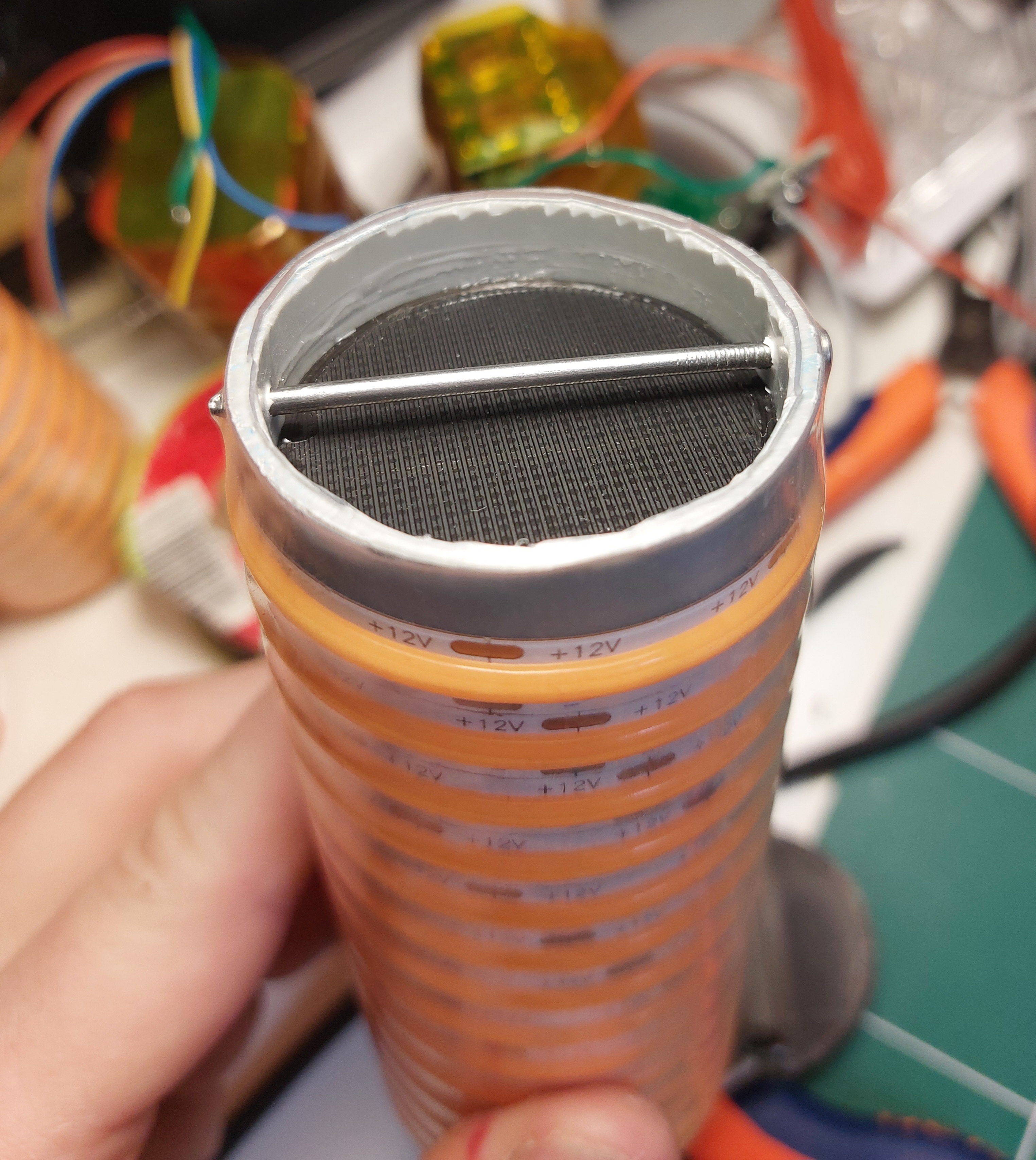
Once the nail is in place, we will wrap the LED around the tube, starting from the side with the nail. It will serve as a guide for winding. Once at the top, cut the strip at the level of the copper connectors.
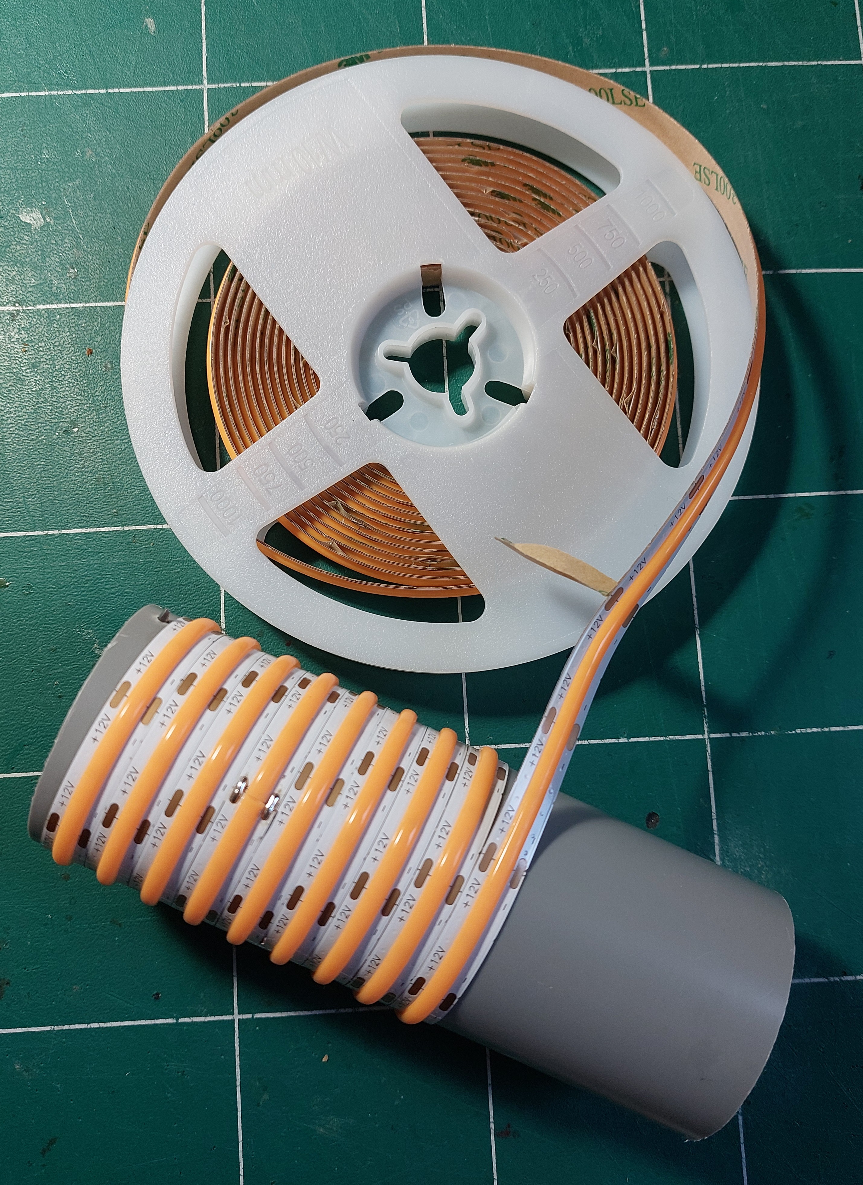
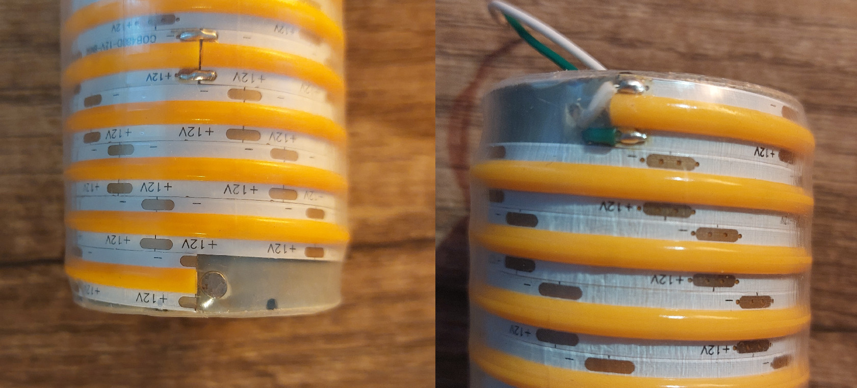
Drill 2 holes at the end of the LEDs (top of the lamp) and pass 2 electrical wires through them; they will be used to power the LED strip. Solder one on the +12V and one on the -. A dab of glue in each hole (nail and LED wires) can be used to seal everything.
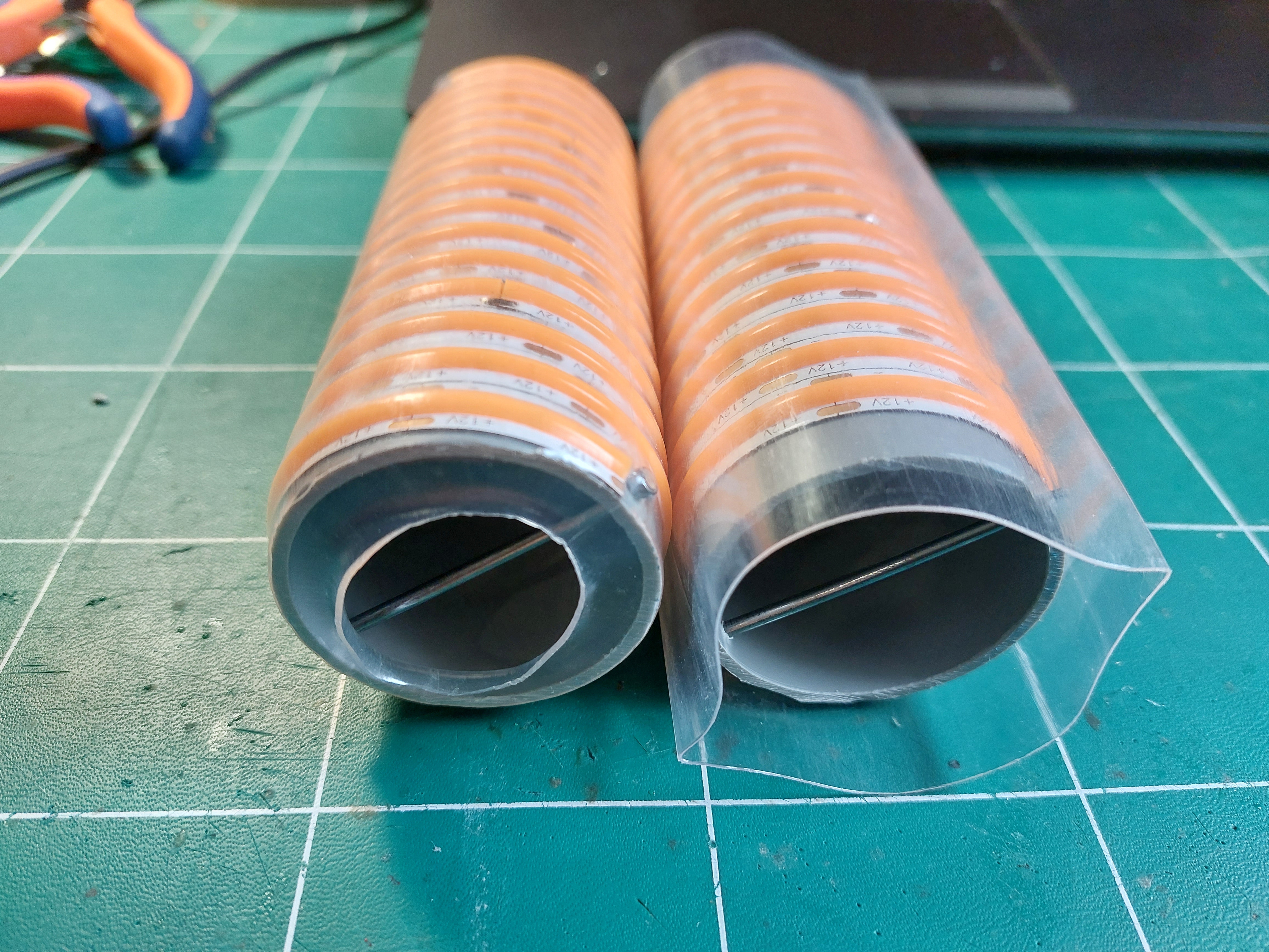
Cut a 15 cm section of heat-shrink tubing and slide it around the tube of our lamp. Using a hairdryer, heat the tubing enough for it to shrink around the tube, forming a kind of casing. Cut off the excess along the tube using a cutter.
Once the heat-shrink tubing is in place, you can install the first 3D-printed piece: the battery bottom. It should be placed at the bottom of the tube but not glued against the nail; there should be a 2mm gap between the piece and the nail. I use a 3D-printed guide to control the distance between the two. Glue the battery guide onto the tube with super glue.
Use the lamp base (3D-printed) to attach the end of the cord to the nail. Once the cord end is installed, generously apply glue between the battery guide and the lamp base without touching the cord. Glue the two parts together, pressing while it dries.
Finished lamp tube!
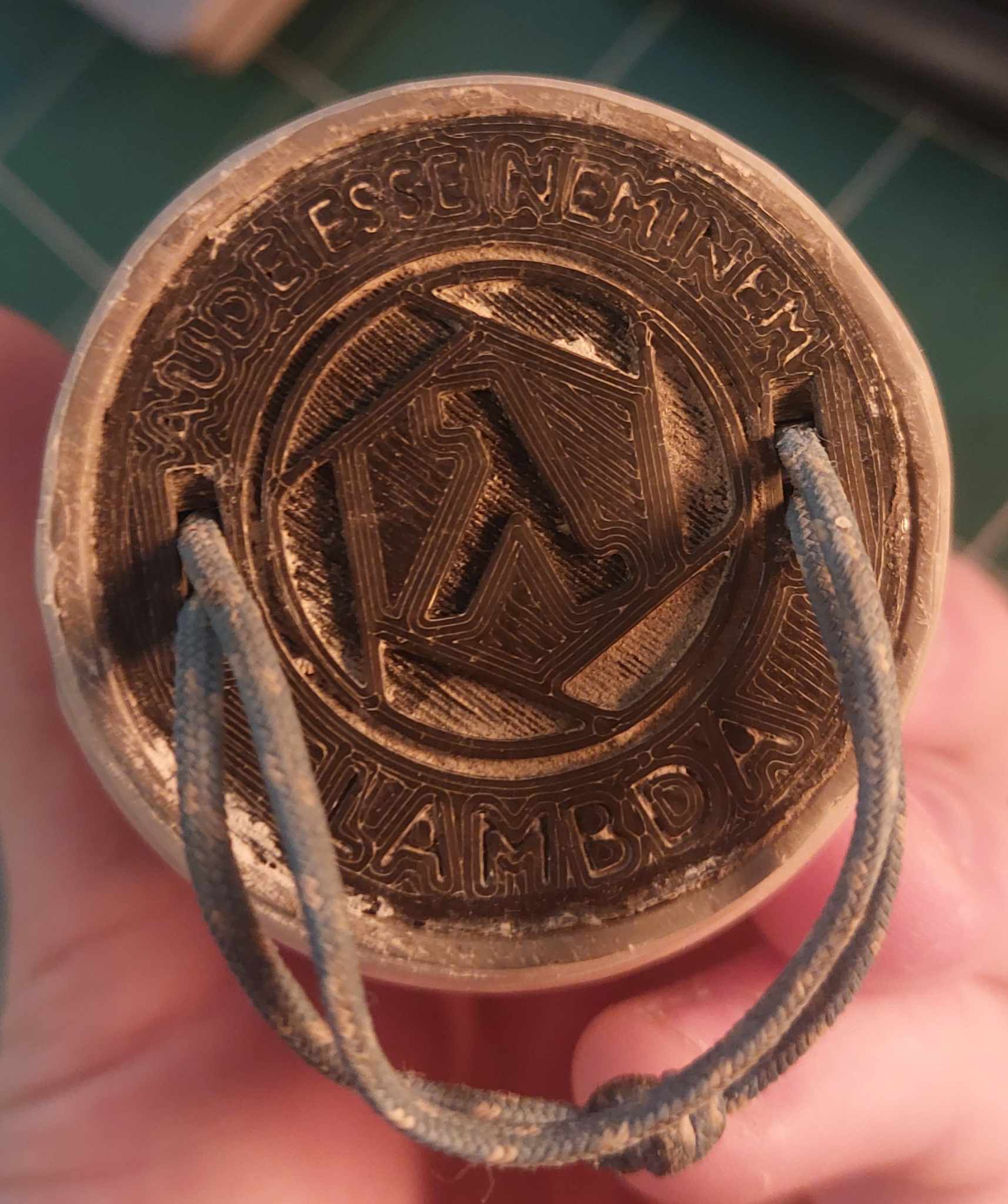 (Yes, this lamp has seen a lot of use)
Top Cap
Use the 3D-printed piece as a base.
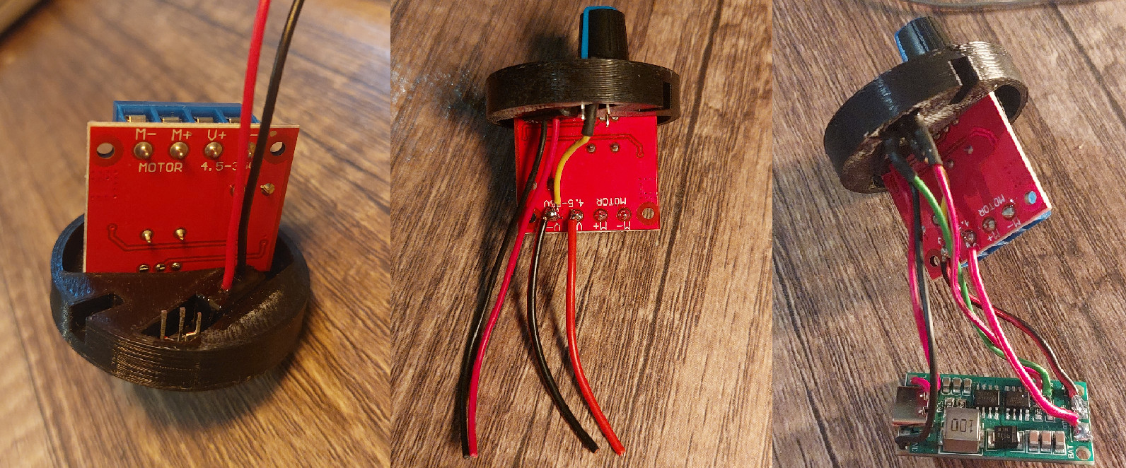
Attach the PWM controller and the waterproof USB-C port in the cap. I recommend gluing the back of the USB-C to the plastic of the cap.
Also, glue the charge indicator LED into the cap.
Don’t hesitate with the glue; this piece is the lamp’s weak point.
Battery Assembly
Be cautious when handling Li-ion batteries; they are sensitive to everything (heat, moisture, deep discharge, overcharge, etc.) and tend to swell/explode if mishandled. See the fire risk protection website There you go, it’s said, good luck:
Start by checking the batteries:
Li-ion batteries have a maximum voltage of 4.2V and a minimum voltage of 2.9V. If your batteries are outside these voltages, there’s a big problem; do not use them. Surround each battery with insulation (tape is sufficient) and add an insulating circle on the positive side.

Begin by charging the 3 batteries with a suitable charger (18650 Li-ion charger). Solder the batteries in series using the following triangular configuration:
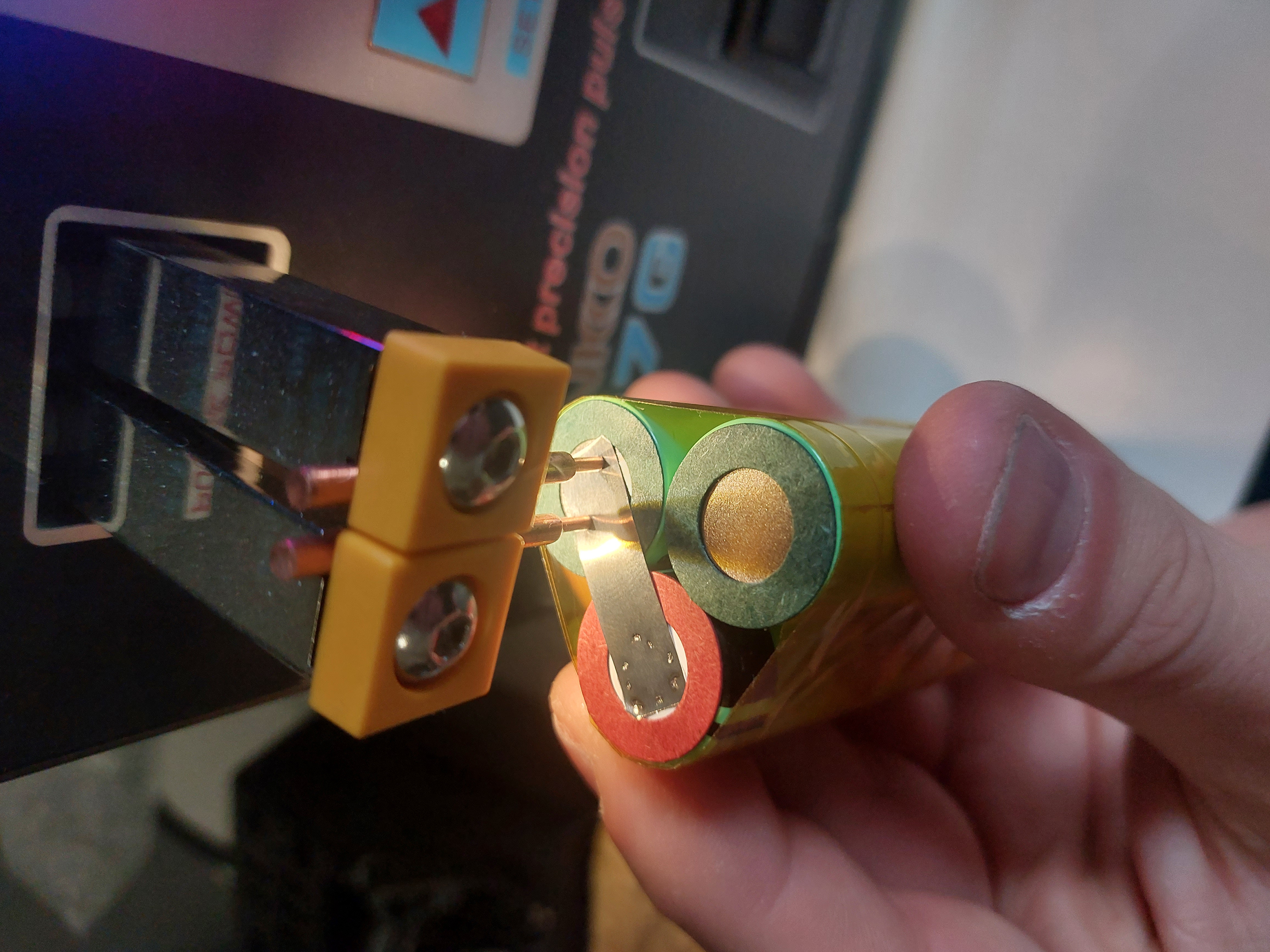
BE VERY CAREFUL; this is the really dangerous step. Solder wires to 0V, 4V, 8V, and 12V, and connect them to the corresponding locations on the BMS. Check three times rather than risking an explosion. Don’t forget to put insulation between the BMS and the batteries!!!
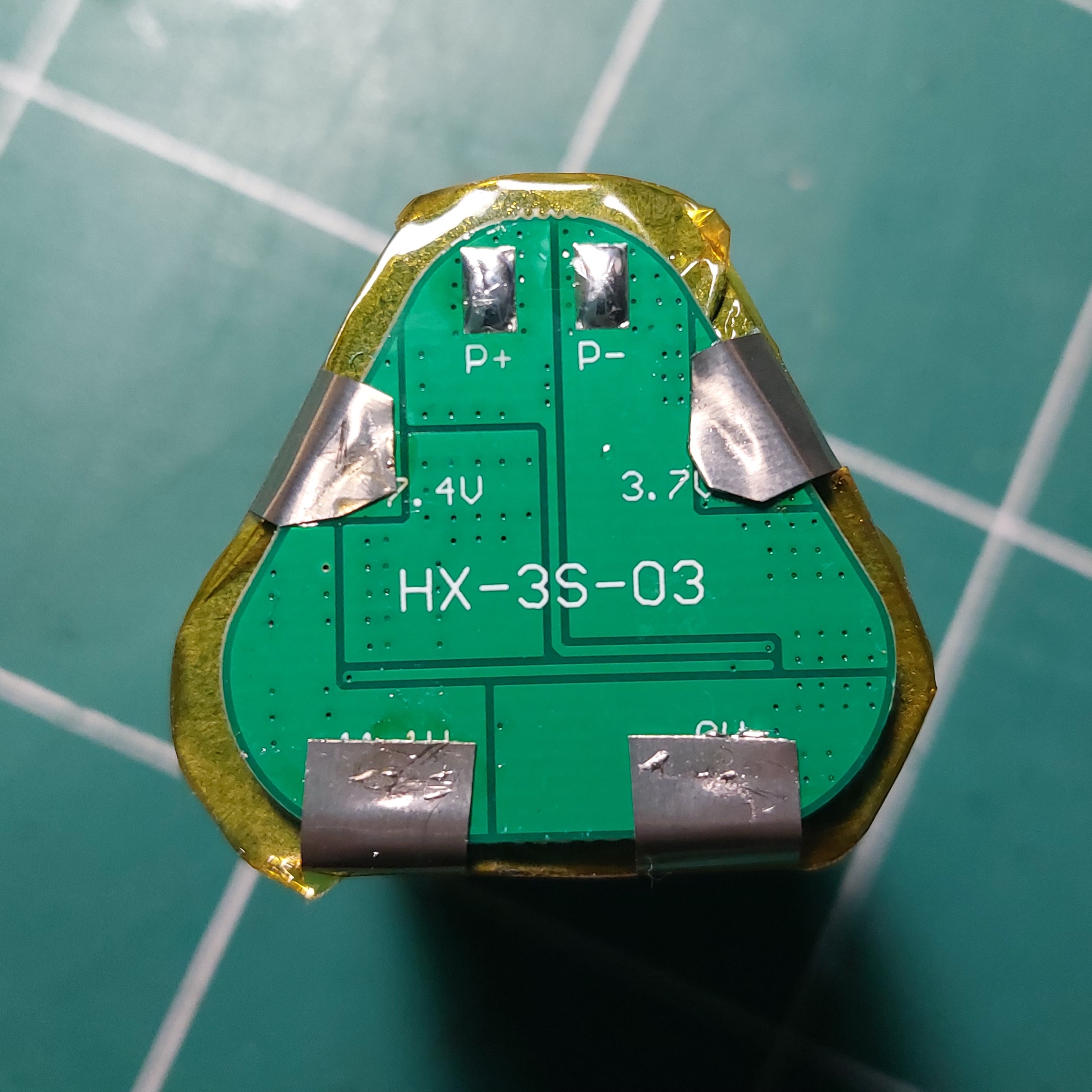
Test the output of the BMS. If it’s >12V, it’s OK. If it’s 0, recheck the connections one by one. If the connections are OK, use a 12V power supply and simultaneously touch the 0 and 12V BMS output with the 0 and 12V of the power supply to activate the BMS.
If there’s no 12V output from the BMS, change the BMS and try again.
Once the BMS is fixed, the battery is secure.
Adding the Balancer
A balancer helps maintain the batteries at the same voltage. This is crucial for the lamp and battery lifespan. Without a balancer, battery voltage will slowly drift between each charge and discharge until one falls to 2.9V while another is charged to 4.2V, causing a BMS lockout (cause: undervoltage) and preventing recharging via the BMS (cause: overvoltage). If it reaches this point, the battery pack is ruined, requiring disassembly and individual recharging. A balancer uses the charge from the battery with the highest voltage to charge those with the lowest voltage, ensuring each battery remains at the same voltage as its neighbors.
Connection
Connect 0V to b0, 4V to b1, 8V to b2, and 12V to b3. Lights on the balancer should illuminate to indicate the balancing function is active.
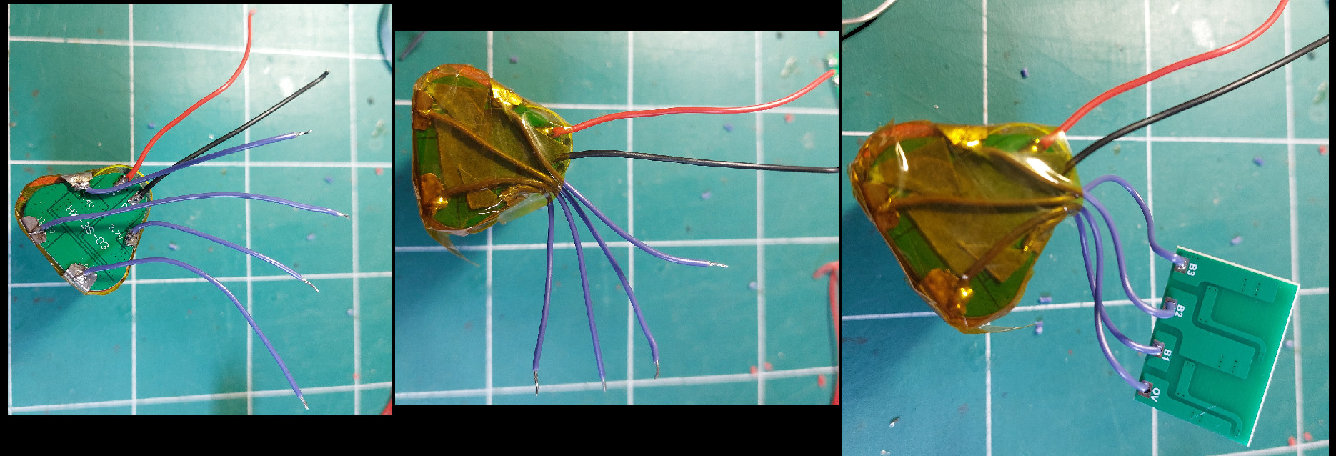
Let it rest until the LEDs are off (be cautious, it heats up during the initial balancing). Normally, if the batteries have been well charged, there shouldn’t be any balancing to do.
I’ve added insulation between the BMS and the wires and avoided crossing the wires above the BMS. In case of significant heating, it’s better to prevent a wire’s plastic from melting and causing a short circuit!
Once the balancer is installed, you can tape the battery to avoid any contact that doesn’t go through the BMS.
Only the two GND and 12V wires should remain.
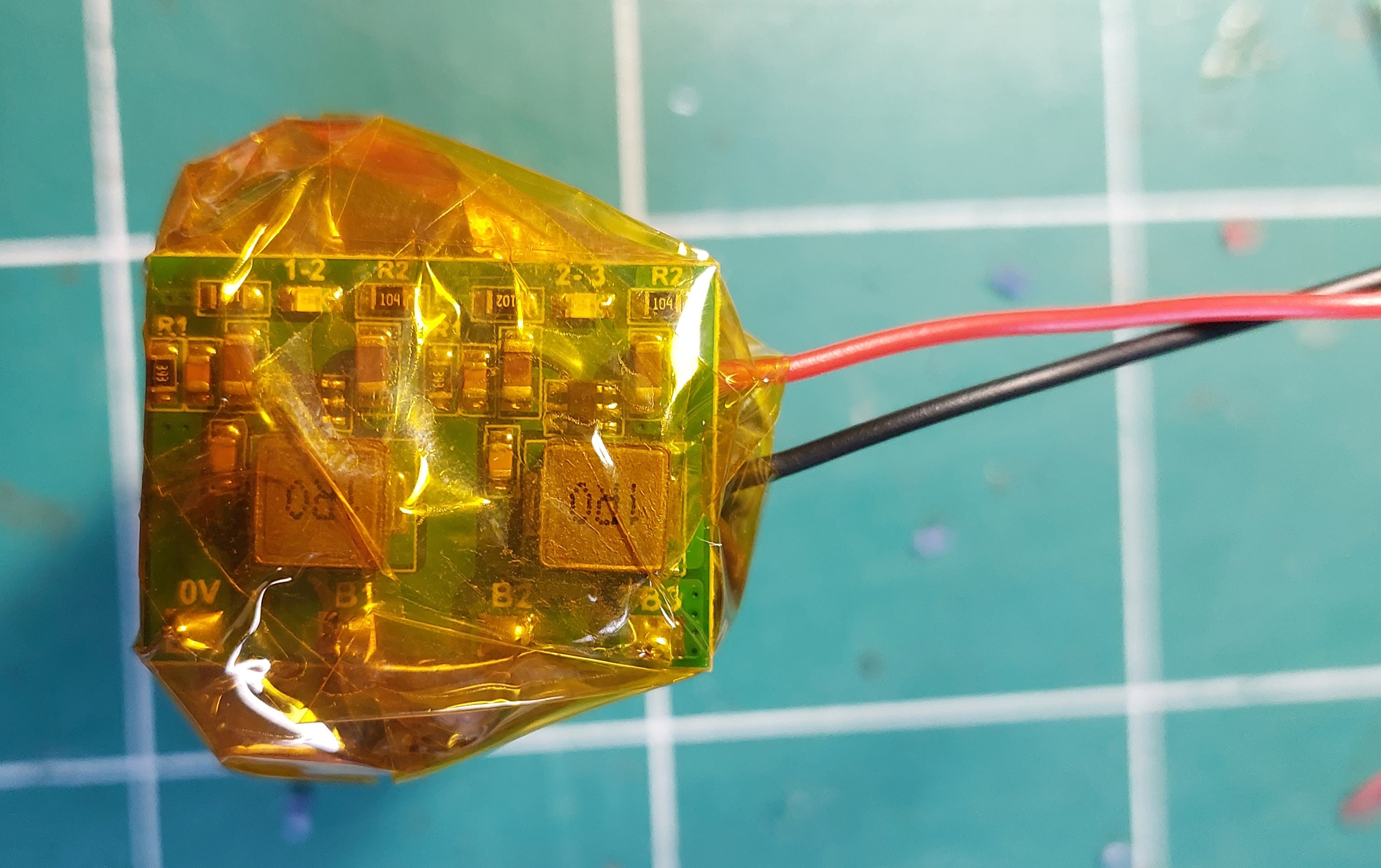
Now, we’re back in the safety zone; the battery should be protected against overcharging, deep discharge, short circuits, and other misuse.
Brightness Controller
 In the image above, the two PWM controllers I’ve tested.
The one on the left is the one I ended up using on all lamps with the charger presented on this page, the one on the right is the one I use with fast charge chargers.
Left:
- 12V 5A max
- Out of the 35 I ordered, 5 simply didn’t work, and one exploded. The rest work perfectly.
- The large green capacitor is used to start a charge with a peak consumption at startup. Because of it, some chargers go into error mode when charging batteries. The LEDs have a small power consumption spike; it should be possible to replace this component with a smaller one.
Right:
- 12V 2A max
- Produces a very brief (10-100ms) bright flash at 100% power when turned on. I find it unpleasant.
- Works flawlessly with all the chargers I’ve tested.
The cap is designed for the left controller.
Connect the - of our battery to the V- of the PWM controller. Connect the + of our BMS to the V+ of the PWM controller. There may be a small spark depending on the type of PWM controller.
Secure the wires by screwing them into the terminal, but I prefer to solder the wires directly onto the PCB; it holds better in the long run.
Turn the PWM potentiometer to activate it. An LED should light up on the controller to indicate that the connections are good.
Test the output voltage: by turning the potentiometer, it should vary from 9V to 12V. If you don’t see any output voltage, or it doesn’t change or changes very little, the component may be defective.
Connect the LEDs: Simply screw or solder the 0 of the LED strip to the M- of the PWM controller and the 12V to the M+. That’s it.
Now you can test the proper functioning of the entire system by applying 12V to the controller input. The LED should be off initially, and the brightness should go from 5 to 100% by turning the potentiometer.
Adding the Charger
Start by testing the charger without connected batteries: the output voltage should be between 12V and 14V (not necessarily stable). A blue LED should light up, indicating that the charging is complete.
Desolder the existing indicator LEDs on the charger and solder our bi-color LED in their place, following the color code in the photo. If we use 45mm tubing, we need to cut the lower corner of the charger (refer to the picture below, next to Bat and GND) or the charger won’t fit flat in the tubing.
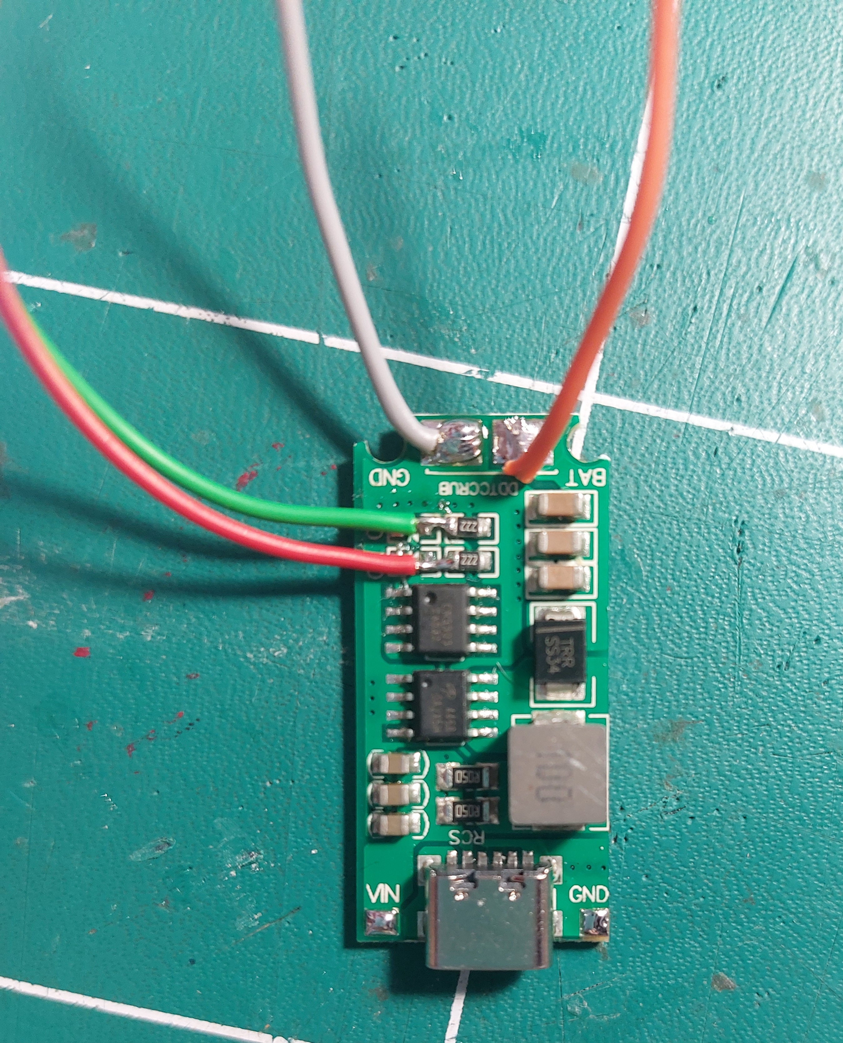
-
The white wire is the - of the system, later connected to the battery and PWM controller. It also serves as - for the bi-color LED.
-
The orange wire is the 12V+, connected to the batteries and PWM controller.
-
The green wire is connected to the green side of the bi-color LED.
-
The red wire is connected to the red side of the bi-color LED.
-
The red wire from the waterproof USB-C connector is connected to the Vin of the charger, and the black wire to the GND.
BATTERIES MUST BE WELDED LAST.
Finalization
Solder the charger GND to the 0V terminal of the BMS, and the BAT to the 12V of the BMS. Connect the charger and check that the batteries are recharging. The indicator LED on the charger indicates the proper functioning of all this.
Since the batteries are already charged, the charging will stop after a few seconds.
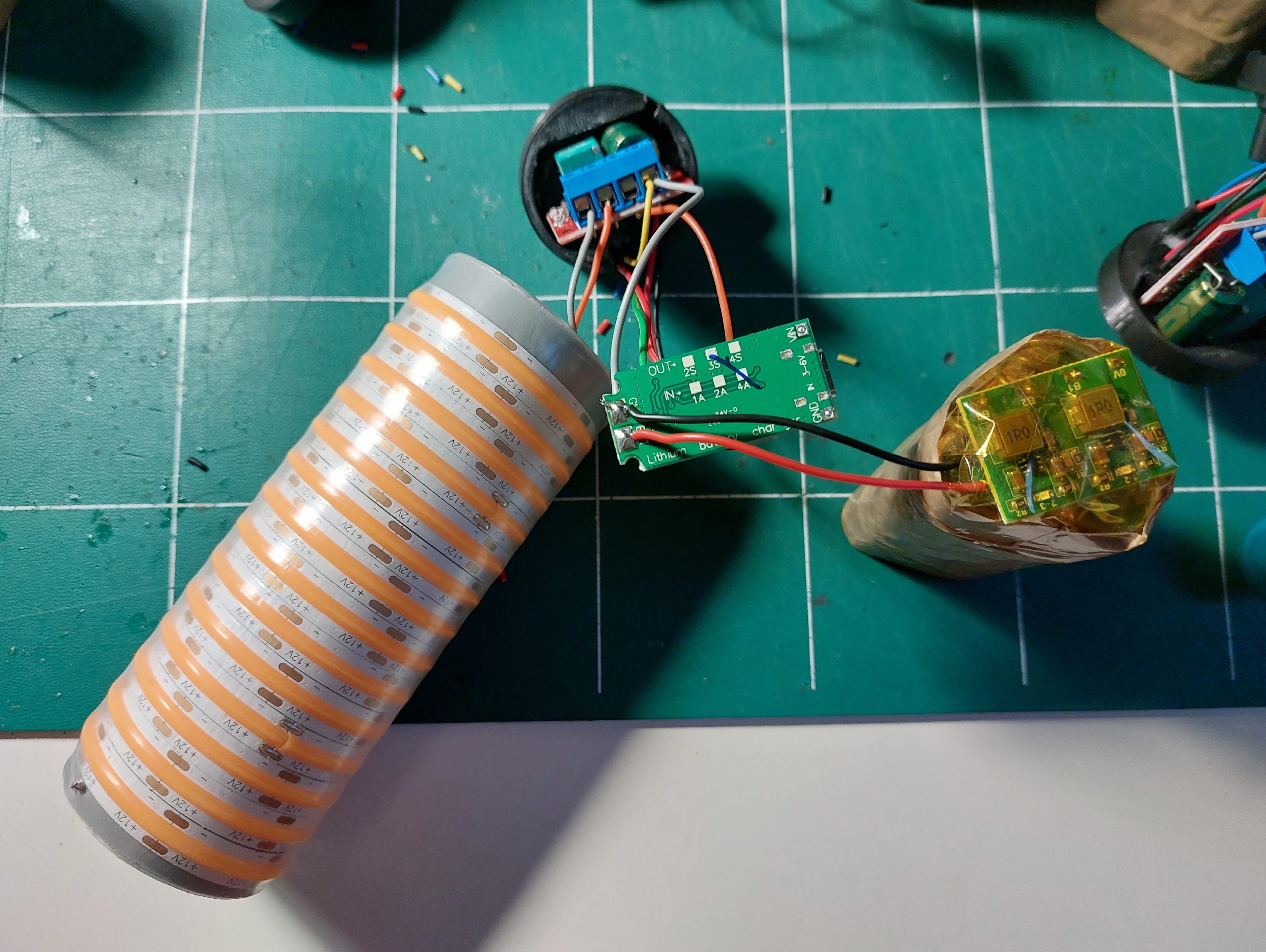
Insert the battery into the lamp tube and secure it well in the battery guide. It can be challenging to insert it into the guide. If there is a blockage, I rotate the pack without using a tool that could damage the battery. I’ve made the mistake before, and PVC burns very well.
Once the pack is secured, you can press the charger against it and close the lamp cap. The cap has an insertion direction: the wires of the LED strip must pass through the cap notch, or it will not close.
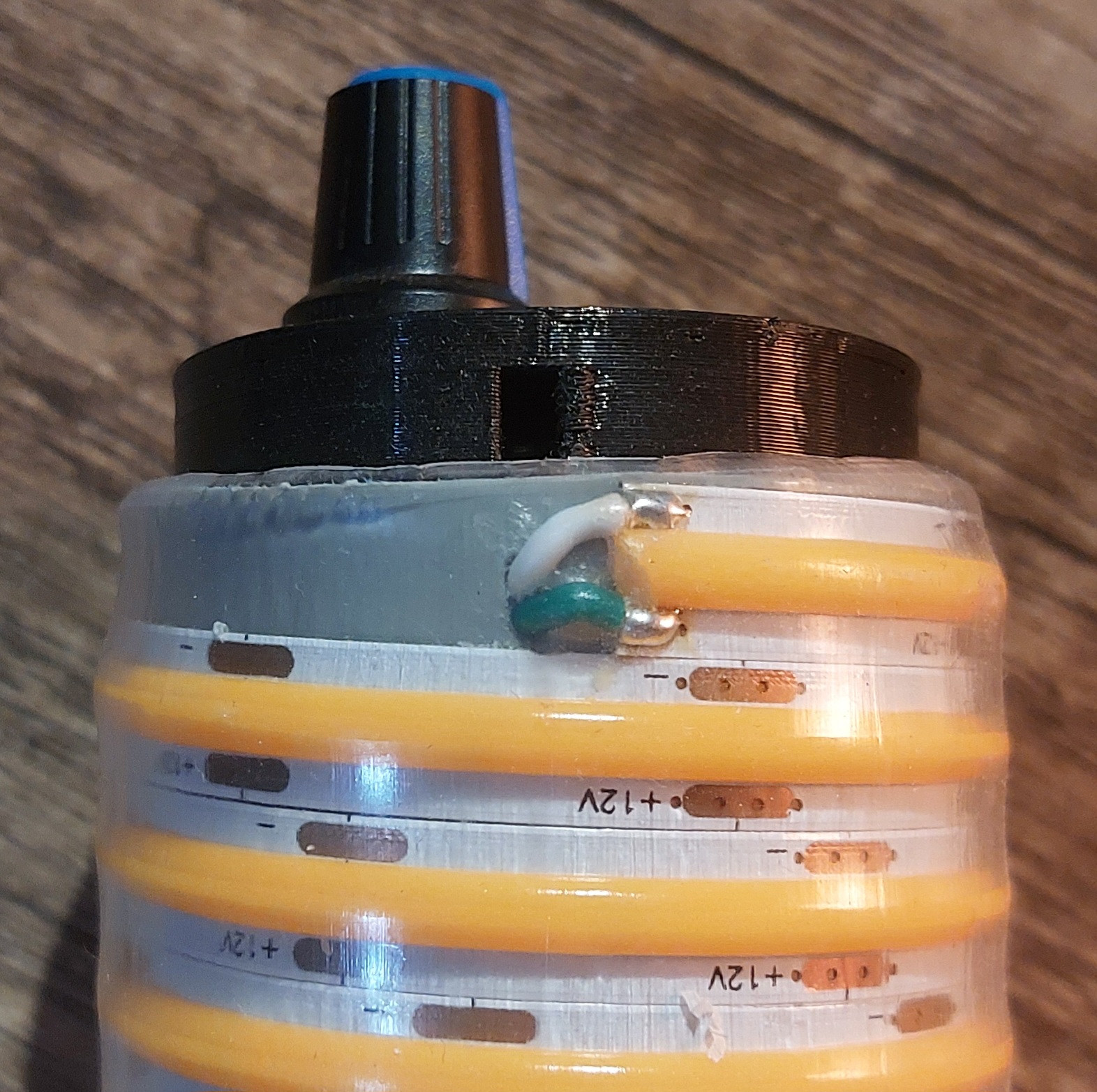
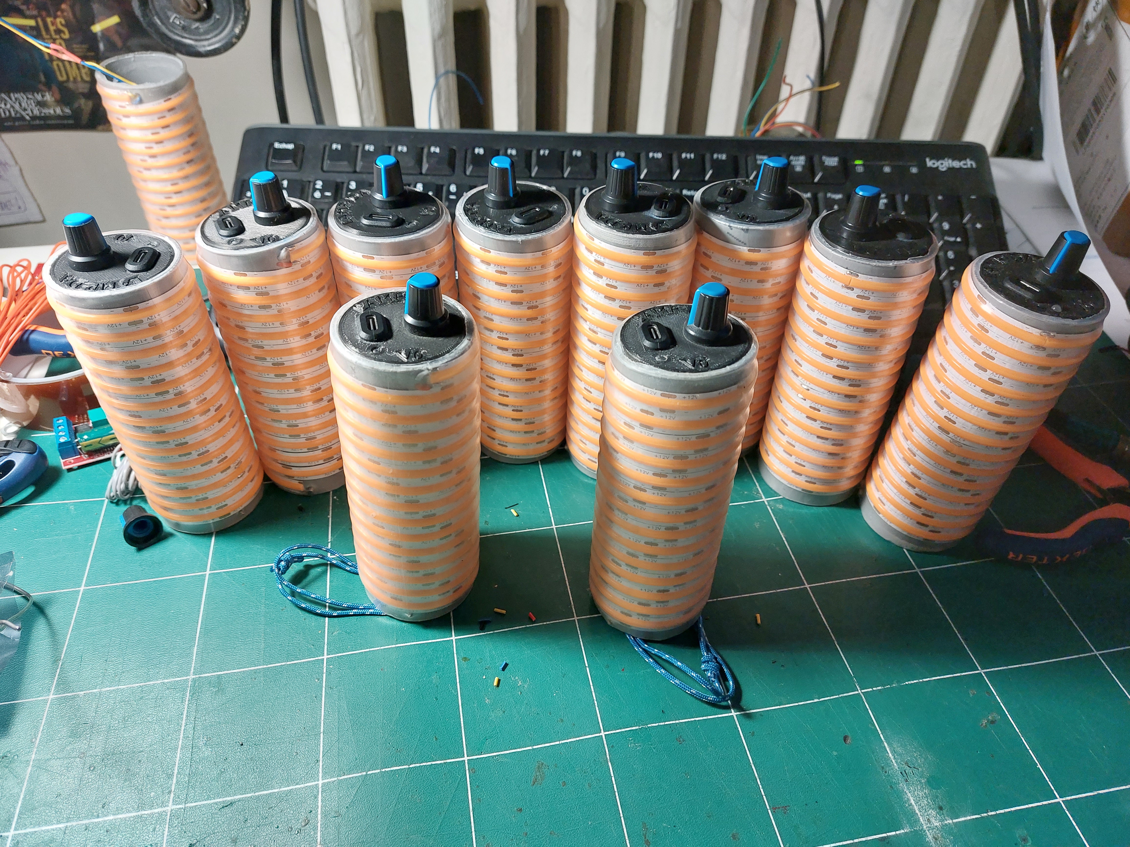
Initially, I don’t glue it and take the lamp for 2 or 3 walks + 2 or 3 recharges to make sure everything works as expected. When you are absolutely sure that everything is functioning, you can glue the cap, spreading glue all around the tube and holding the cap until it dries.
Customizing Your Logo
Create a black and white logo that isn’t too complicated (3D printing has limited resolution). The black part will be the deep section.
Transform this logo into a vector image (.svg); for this, I use Inkscape. Open the file “lampv0_bottom_logo” with Blender (File > Import > STL (Experimental)). Open the SVG logo in the same Blender window (File > Import > Scalable Vector Graphic (SVG)).
Move the logo to the surface of the piece, adjust the scale and orientation. Once the logo is in place, right-click on it, convert to mesh.
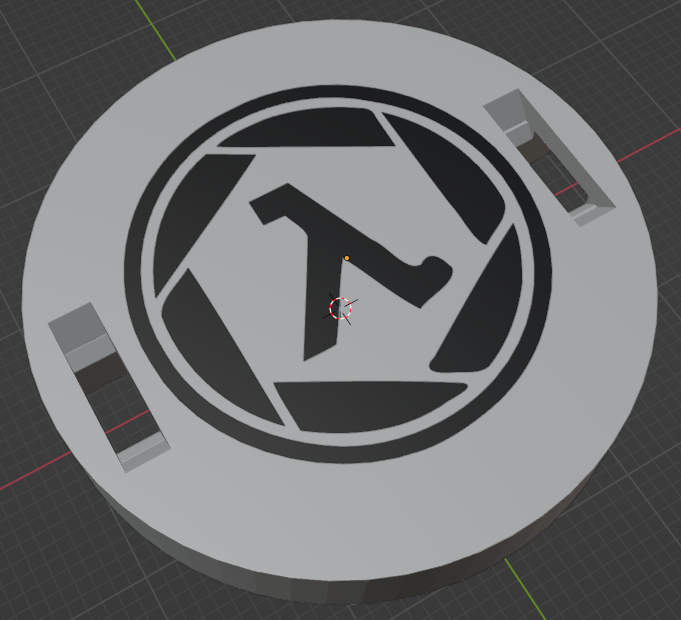
Modification: solidify, with a size of 10m.
- If the SVG is well-structured, this step will work directly.
- If the SVG is malformed, vertical spikes will be observed in the logo. You’ll need to go back to Inkscape to correct this; it’s often caused by SVG nodes without control handles.
Once the logo is correctly transformed into a solid, apply a boolean modification to the lamp base. We specifically want a boolean negation. The logo should be recessed into the surface by 1mm or less, or it risks protruding beneath the piece. Apply and then delete the extruded logo.
Export the result in STL.
Print it with your equipment!
Weak Points
Unfit charger module
The only significant weakness of this system is its charger. I chose to use a 5V charger rather than a fast charge-compatible one to make everything waterproof, but it comes with a few issues:
- The charger only accepts 5V, so no conventional phone charger.
- During charging, the charging component becomes hot to the touch. And it is very close to the batteries.
Li-ion batteries don’t like heat, especially during the charging time.
During charging, the green LED lights up, then it gives way to the red when the charge is complete. If the green or red LED flashes, it means the charger used doesn’t have the 5V setting or the required power. During charging, the body of the lamp should be warm to the touch; if not, the charger is not working correctly. It can be a problem with the charging cable, the charger, or, in the worst case, a component of the lamp.
It’s straightforward to adapt the system to use a fast charge-compatible charger, at the expense of waterproofing. Good luck!
Structural failure point
The lamp also has a weakness (seen once), where during a fall, it falls vertically on the potentiometer of the PWM controller, breaking the axis. The lamp still works, but there is no longer brightness regulation (it goes from off to 100% brightness). 99% of the time, the plastic cap will break of, saving the potentiometer. Just need to glue it back on, easy enough!
Luminosity drop in use
During use, the maximum brightness gradually decreases with the battery level until it reaches the minimum. Users have told me that this is somewhat positive as it allows them to check the battery level, and it is not noticeable. Still, it remains a flaw in my opinion.
Under charge handled by BMS
Another minor design flaw: if the battery discharges below the safety limit (3V), the BMS will cut off the lamp (which is pretty cool, that’s its job). The concern is that the battery is then in a critical state of discharge and needs to be recharged quickly, otherwise it will start degrading. In practice, the lamp lights up very little in the last 5% of the battery, so we need to recharge it before it gets too low, before it’s in a critical state, which is not really a problem. We could even argue that it should stay at 2.8V and give us some time to charge it after being cut off, even after putting it back into safety mode.
Ideally, the lamp should be cut off at 3.2V to ensure that the battery stays charged until it’s plugged in
Thank you for following until now, good luck on your dark explorations!